
| EXPLORE OUR THEME ON: EPS, FLAT ROOFS, PV PANELS & FIRE SAFETY | Use our drop down menu to quickly navigate the theme: |
European large-scale tests with solar panels on flat roofs. Watch the film, and see how the layer beneath the membrane affected fire spread and heat exposure of the insulation. In a European test series, flat roofs with solar panels were burned at full scale. The aim was to examine how the build-up beneath the roof membrane affects a fire that starts beneath the modules. The tests were commissioned by EUMEPS and IVH (Industrieverband Hartschaum), carried out by Kiwa BDA at Twente Safety Campus in the Netherlands and analysed by DBI.
Watch a film of several of the tests here:
In brief
- Large-scale tests on 7 × 7 m roofs and six medium-scale tests with one module. The film above shows three different tests: EPS with coverboard, A1 Mineral Wool with and without a the same coverboard.
- With a 12 mm cement-bonded board between PVC membrane and EPS, no self-sustained fire developed in three of four tests. In all four, the EPS was affected only locally beneath the burner.
- With the PVC membrane laid directly on mineral wool, without a board, the fire spread beneath the whole module array.
- At medium scale, an 8 mm board gave the same result on EPS and on mineral wool. It is the layer directly beneath the membrane that is decisive, not the insulation’s class alone.
- The tests are research and development tests.
How the tests were carried out
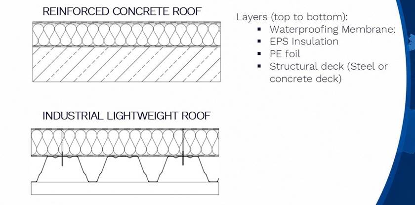
Figure 1. The two types of flat roof in the tests: concrete deck and lightweight roof with profiled steel deck. From the top: roof membrane, EPS insulation, PE foil and load-bearing deck. Source: EUMEPS.
The roof build-ups were 7 × 7 m with an east/west-oriented array of 4 or 12 modules. The fire was started with a 15 kW gas burner beneath the edge of a module for 10 minutes, as described in CLC/TR 50670. Horizontal fire spread and roof damage, vertical penetration into the roof build-up and temperatures between the layers were measured.
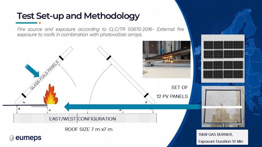
Figure 2. Test set-up: 15 kW gas burner beneath the edge of a module for 10 minutes, roof surface 7 × 7 m, 12 modules in east/west configuration. Source: EUMEPS.
EPS with 12 mm cement-bonded board
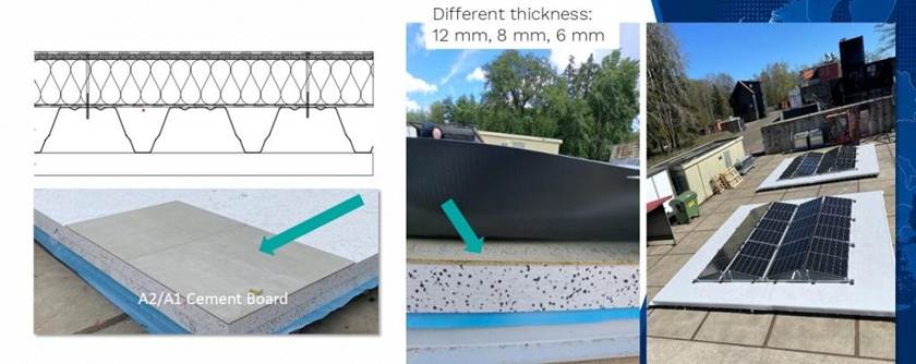
Figure 3. Build-up with cement-bonded board between membrane and EPS. The board was tested in 12, 8 and 6 mm. Source: EUMEPS.
Four tests had PVC membrane, 12 mm cement-bonded board and EPS. In three of them, no self-sustained fire developed, and the membrane was damaged only locally around the burner (at most 1.7 × 1.3 m). In the fourth, the fire spread beneath all modules. DBI links this to stronger wind. In all four, the EPS was affected only directly beneath the burner.
A fifth test with bitumen roofing instead of PVC gave fire spread beneath all modules. Here too, the EPS was affected only locally beneath the burner.
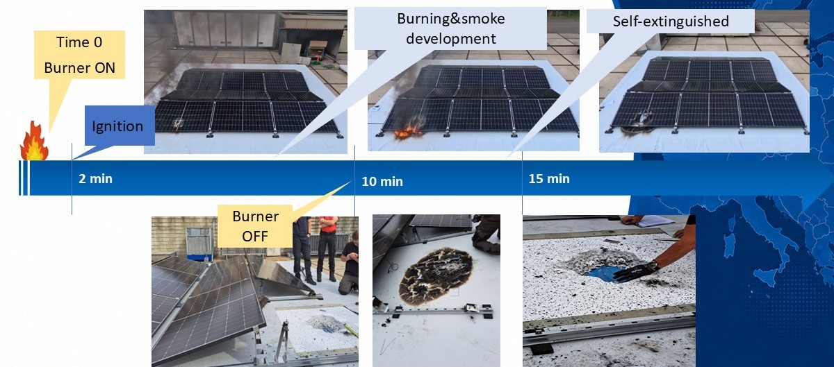
Figure 4. One of the tests with 12 mm board where the fire did not spread: timeline from ignition to self-extinguishment, and the roof damage afterwards. Source: EUMEPS.
On the top of the board, close to the burner, the temperature exceeded 800 °C. At the instrumented measurement points beneath the board, the temperature was at or below about 100 °C. The temperatures apply to the specific measurement points and do not necessarily show the highest temperature directly beneath the burner. DBI considers that the temperature of about 100 °C is probably due to the chemically bound water in the board evaporating and absorbing energy. Once the water has gone, the temperature rises again.
NEPSA and the Danish EPS Association work with a preliminary target that the temperature on the top of the EPS should not exceed 150 °C. Below that temperature EPS does not become liquid and therefore cannot run down and contribute to the development of the fire. The target is our own proposal for an acceptance criterion. At the measurement points beneath the 12 mm board, the temperature stayed below the target.
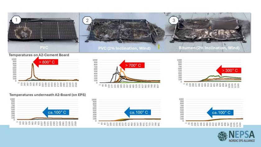
Figure 5. Three tests with 12 mm cement-bonded board on EPS: tests 1 and 2 with PVC membrane, test 3 with bitumen roofing. Top: membrane damage after the test. Middle: temperature on the top of the board, above 800, 700 and 300 °C. Bottom: temperature beneath the board, on the EPS, about 100 °C in all three tests. In tests 2 and 3 the fire spread beneath the modules. Data: Kiwa BDA test reports for EUMEPS and IVH.
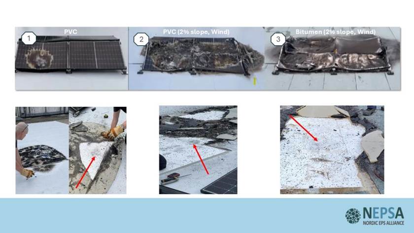
Figure 6. The EPS beneath the board after the three tests in Figure 5. The arrows show where the EPS has retracted locally beneath the burner. The rest of the insulation is unaffected.
Mineral wool without board
In this test, the PVC membrane lay directly on 120 mm mineral wool. The fire spread self-sustainingly beneath the module array and on from one section of the array to the next. Kiwa BDA stopped the test after 11 minutes for environmental and safety reasons. The membrane was damaged over a large area, and the mineral wool was heat-affected beneath the fire area.
The build-up had no protective board. The test is therefore not a like-for-like comparison of insulation materials, but shows the importance of the layer beneath the membrane.
Mineral wool with board
A large-scale test has also been carried out with a 12 mm cement-bonded board over mineral wool.
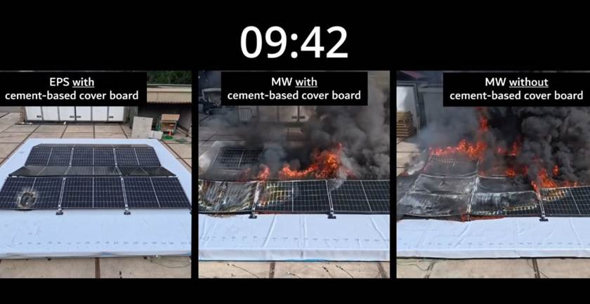
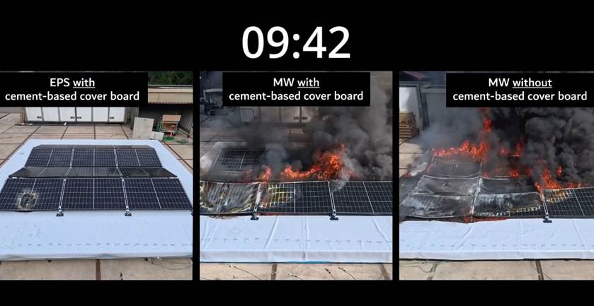
Figure 7. Three large-scale tests 9 minutes and 42 seconds after ignition: EPS with cement-bonded board, mineral wool with cement-bonded board, and mineral wool without board. The tests were not carried out on the same day.
In the recordings, the board limited horizontal fire spread compared with mineral wool without a board. Spread was nevertheless greater than in the test shown with EPS and board, where the fire went out. In DBI’s medium-scale tests with an 8 mm board, the result was the same on EPS and on mineral wool. The observations are based on video and photos from the test.
Thinner boards
In two large-scale tests, the 12 mm board was replaced by an 8 mm cement-bonded board and a 6 mm cement board. The fire did not spread in either, and only one module was affected. On the other hand, the EPS retracted further beneath the burner, up to 10 cm, and the vapour barrier got local holes. The highest temperatures measured beneath the board were 48 and 76 °C, but no measurement points were close to the ignited area.
The holes were caused by melting of the vapour barrier, not by flame penetration. NEPSA and the Danish EPS Association use an intact vapour barrier as a sign that no vertical burn-through has occurred. By that criterion, the tests with 12 mm board met the target: Kiwa BDA’s reports mention no damage to the vapour barrier, and the temperature on the steel deck was unchanged. The tests with the thinner boards did not.
Whether thinner boards can meet the criterion with a thicker layer of EPS requires specific testing. Until then, NEPSA and the Danish EPS Association consider a 12 mm board the most appropriate choice. In the tests, it prevented vertical fire spread.
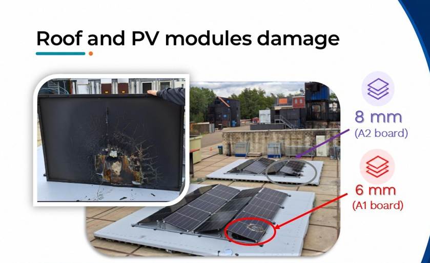
Figure 8. Tests with 8 mm and 6 mm board: only one module was affected in each test. Source: EUMEPS.
DBI also carried out six medium-scale tests indoors with one module. With a board, including an 8 mm board on mineral wool, the fire went out when the burner was switched off. Without a board, with the membrane directly on mineral wool, the fire spread beneath the module in both tests. DBI considers that the insulation beneath the board had no influence on whether the fire spread.
The system effect
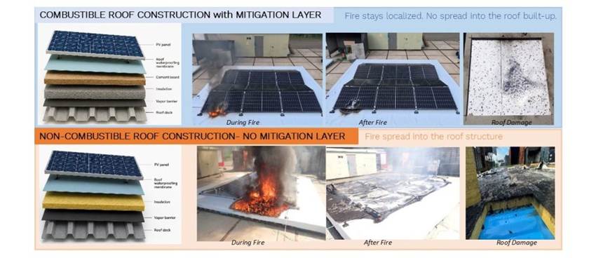
Figure 9. Same fire exposure, two build-ups. Top: EPS with cement-bonded board beneath the membrane, one of the three tests without spread. Bottom: membrane directly on mineral wool without board. In one of four tests with board on EPS, the fire also spread beneath the modules. Source: EUMEPS.
DBI explains the difference as follows: a dense, cement-based layer absorbs energy from the zone ahead of the flame front. The thin membrane therefore does not reach its ignition temperature, and the flames go out.
What the tests show, and what they do not show
The tests show that a protective layer with a documented effect can change the course of the fire significantly in the build-ups tested. They also show why a roof’s fire safety has to be assessed as a system: the same insulation material can give different results depending on the layer above it.
The tests were not carried out to a standardised method, comprise a limited number of tests and were affected by wind. The results apply to the specific build-ups, materials, dimensions and test conditions. A relative improvement is not the same as a defined level of safety. Whether the results are good enough depends on acceptance criteria for penetration, horizontal spread and fire development over time, which have not yet been set. Read more in the position paper and about the fire dynamics beneath solar panels.
About the tests
The tests were commissioned by EUMEPS and IVH, who also determined the roof build-ups. Kiwa BDA carried out the large-scale tests and prepared the test reports. DBI witnessed the tests, analysed reports, video and temperature data, and carried out the medium-scale tests. Sources: DBI (2026). Large-scale tests of flame spread on roof build-ups with PV systems: A white paper. SIEC21006-003. DBI (2026). Large-scale tests of flame-spread on roof build-ups with PV systems: Phase III. SIEC21006. Kiwa BDA, test reports 24L0474, 25L0053 and 25L0198.